
With Home Assistant installed we can now add a first interface which will be control of the lights. This
will involve some wiring, soldering, and circuit work, so a basic understanding of circuits is recommended. We'll
need a few items for this to work:
- Raspberry Pi Starter Kit: If you're new to electronics, I recommend picking up a starter kit for the raspberry pi similar to this one. It comes with some basic electrical components, wires, a breadboard, and a GPIO extension board which will be very useful for prototyping circuits
- Soldering Iron: A basic kit like this one will do the trick if you don't have a soldering iron already
- Multimeter: It's always a good idea to check for shorts with a multimeter before powering up any circuits. It's also a great debugging tool. I had a cheaper one, but it was unreliable and it eventually broke, so I upgraded to a more reputable brand like Fluke
- N-Channel MOSFETs: These will be used to switch on and off the lights
- Lights: I use these 12V LED lights in my van
The Raspberry Pi GPIO pins operate at 3.3V, so they can't be used to drive our lights directly. Instead we
need a way to use the GPIO pins to switch on and off a 12V source to the lights. We will do this using an
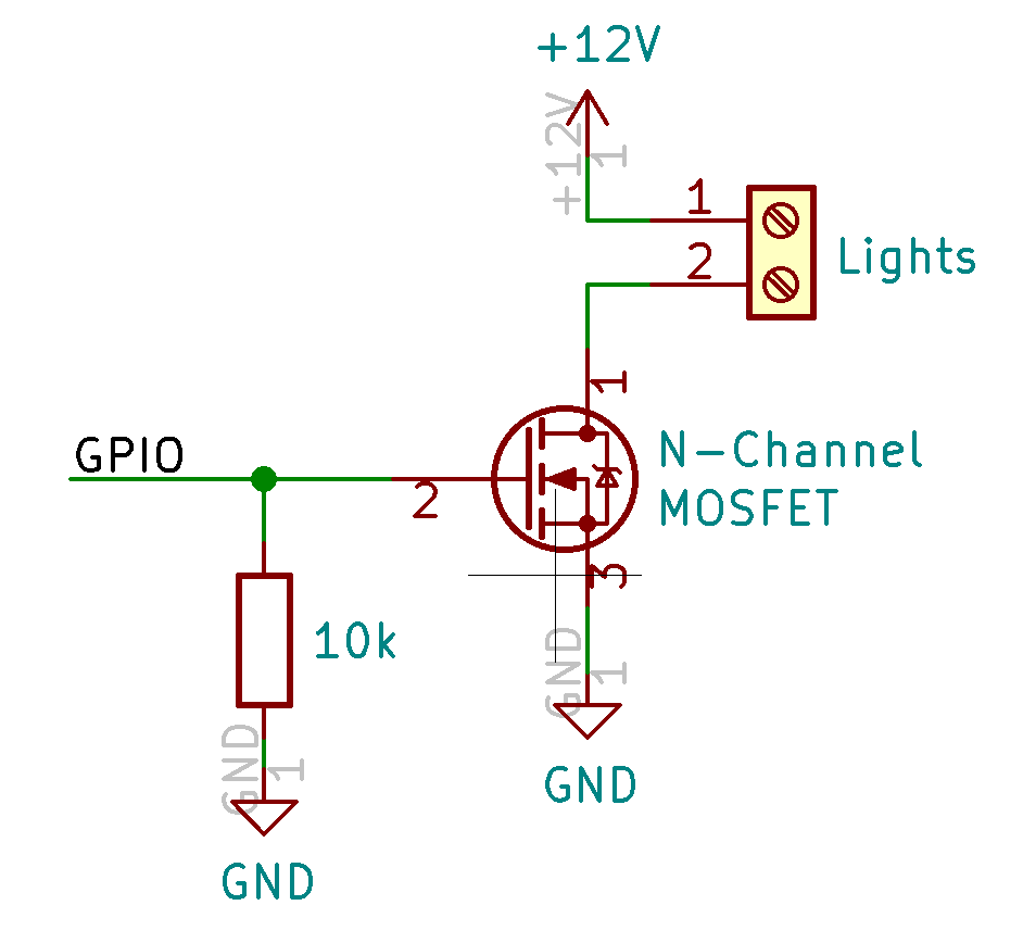
N-Channel MOSFET. Here is the basic circuit:
The GPIO pin from the Raspberry Pi drives the gate of the MOSFET (pin 2 above).
If the voltage on the gate exceeds the gate threshold voltage, the MOSFET will turn on allowing current to flow from
the drain (pin 1) to the source (pin 3). Make sure the gate threshold voltage on the MOSFET that you use is less
than 3.3V or the Raspberry Pi will not be able to drive it. A 10k resistor is also added between the gate and ground
to keep the MOSFET turned off if the GPIO pin is not configured correctly.
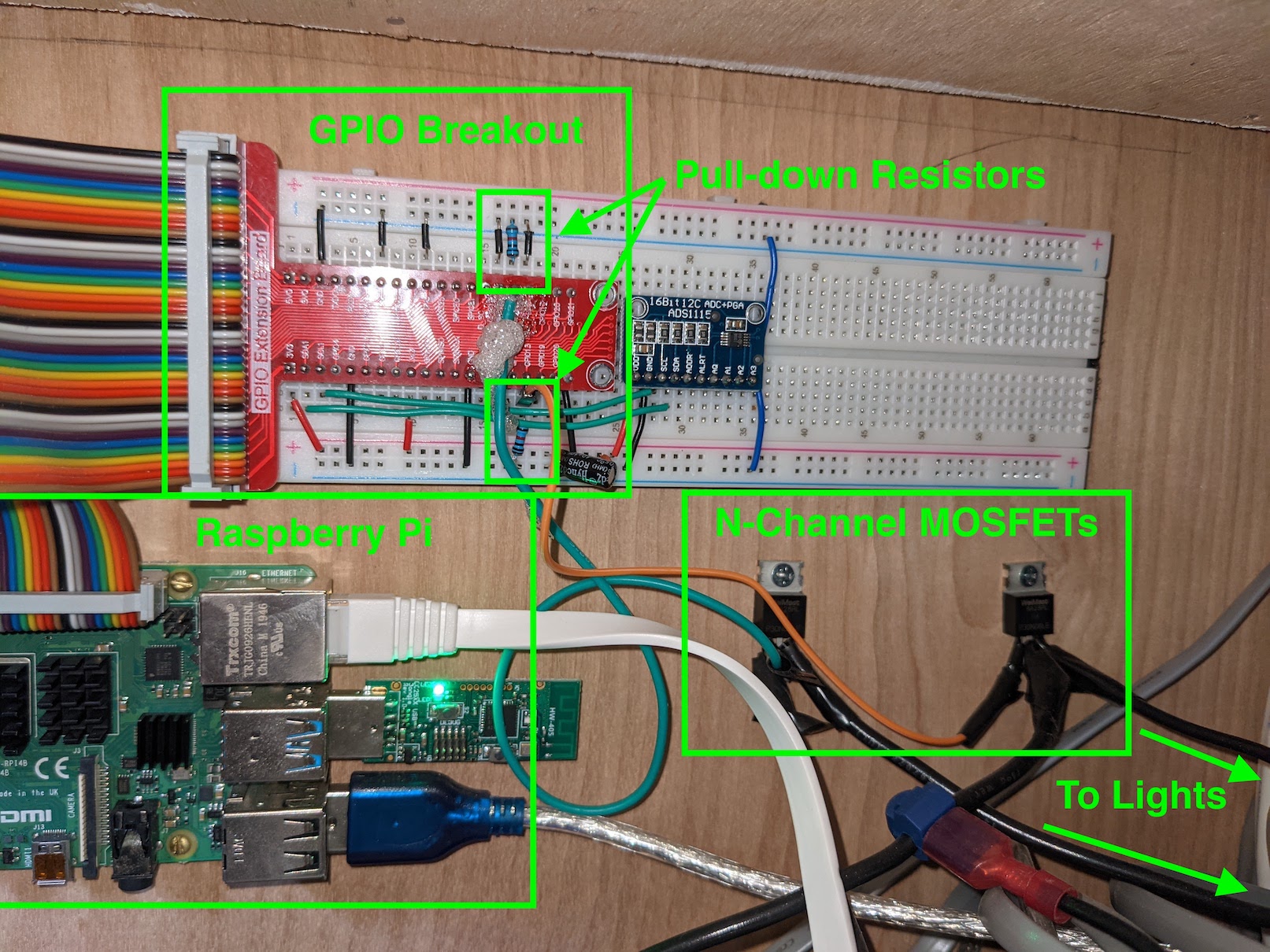
I put this circuit together by soldering wires directly to the MOSFETs and connecting the gate wire to a
breadboard where I have the 10k resistor and the GPIO extension board which connects it back to the Raspberry Pi.
It's a little hacked together, but it works. I plan on eventually putting this together onto a PCB to clean things
up a bit.
For the GPIO pin, make sure you use GPIO12, 13, 18, or 19 since these are the hardware PWM pins on the
Raspberry Pi that will allow for dimming. I used 12 and 13 and replicated the circuit twice since I have two different
zones for the lights in my van.
Next we need to set up the Raspberry Pi to be able to control these GPIO pins. We need to first install
and enable pigpiod:
sudo apt-get install pigpio
sudo systemctl enable pigpiod
sudo systemctl enable pigpiod
We then need to enable remote GPIO on the Raspberry Pi. Enter the raspi-config utility:
sudo raspi-config
Choose option 3 - Interface Options, then option P8 - Remote GPIO, then Yes to enable. Exit out and
reboot the Raspberry Pi for changes to take effect.
The last step is to add the light entities to Home Assistant. Navigate to your home assistant directory
(/home/pi/homeassistant in my case). Add the following to your configuration.yaml file:
light:
- platform: rpi_gpio_pwm
leds:
- name: Bed Lights
driver: gpio
pins: \[12]
type: simple
frequency: 50000
- name: Main Lights
driver: gpio
pins: \[13]
type: simple
frequency: 50000
- platform: rpi_gpio_pwm
leds:
- name: Bed Lights
driver: gpio
pins: \[12]
type: simple
frequency: 50000
- name: Main Lights
driver: gpio
pins: \[13]
type: simple
frequency: 50000
This configuration is for two light zones, one controlled by GPIO12 and one by GPIO13. You can change the
names and pin numbers to match your configuration. For the frequency, I played around with it until I found a
value that worked well. Too low and you can notice the lights flickering when dimmed. Certain values also seemed
to cause a high pitched ringing noise from the lights.
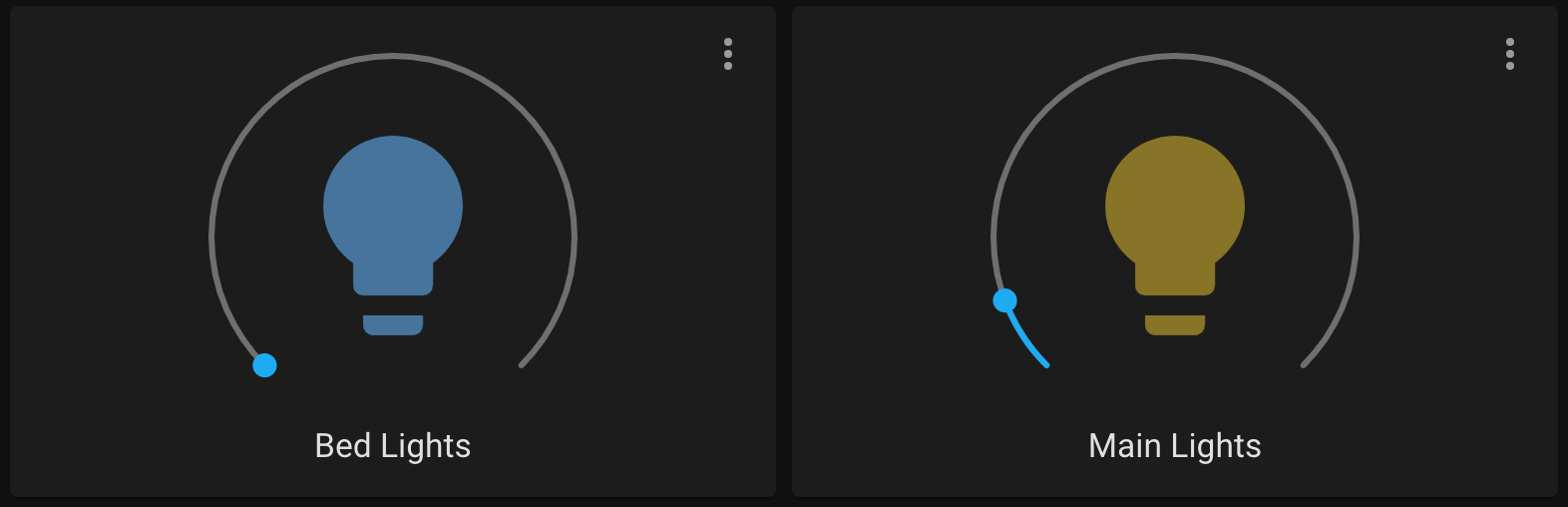
After restarting home assistant you should be able to edit the dashboard and add a light card to control
your lights!
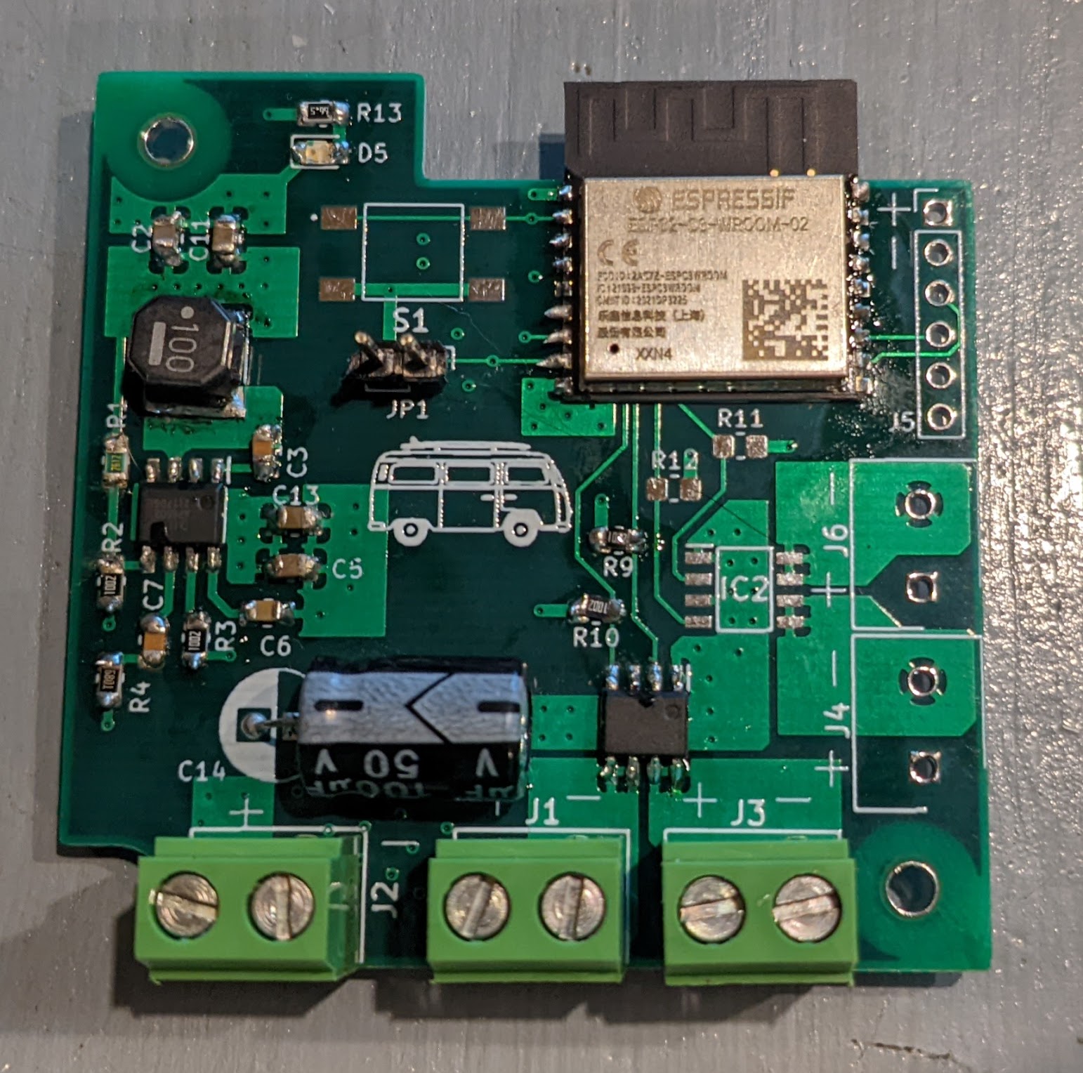
Update: I designed a custom PCB using an ESP32 microcontroller to control the lights so I could
clean up the wiring around the Raspberry Pi. I used the same basic circuit as shown above, but with the PWM
outputs coming from the ESP32 instead of the Raspberry Pi. The KICAD files for the PCB can be found here:
I had originally planned to use ESPHome for the software on the ESP32, but I designed the PCB to use
the latest C3 version of the ESP32 which wasn't supported by ESPHome yet. Because of this I ended up writing my
own software in C for the ESP32. The code can be found here:
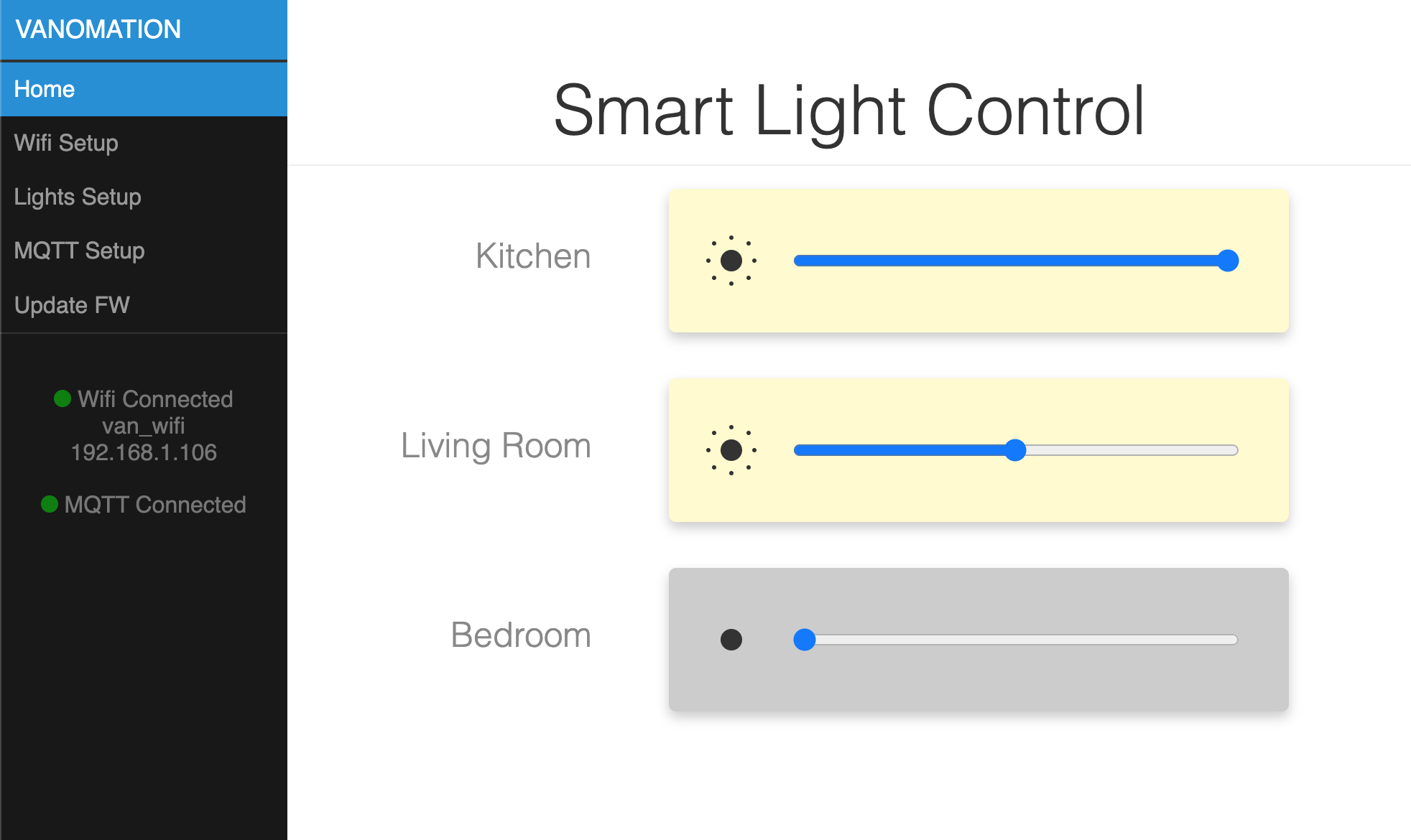
With this code on first startup, the ESP32 starts in softAP mode and hosts a webserver. From the web interface,
you can configure the device to connect to a wifi network, enable/disable and rename the 4 lights, and connect the device
to an MQTT server. With the MQTT integration installed in Home Assistant, the lights should configure and show up
as devices within Home Assistant automatically! Below is the web interface hosted by the ESP32.