The next sensor that I thought would be useful in the van was a level sensor to see how flat
the van currently is. When parking for the night, it's always more comfortable to sleep if the van is level. I
would always find myself using rocks or inching forward and backward and ask myself "is it better now?". The easy
solution would be to just stick a bubble level somewhere, but I thought it would be much more interesting to
incorporate it into my Home Assistant setup.
Items needed to set this up:
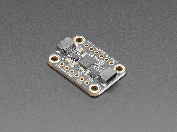
- MPU6050 Accelerometer: This device essentially measures gravity on 3 axes and can tell you which way is down. It also has a gyroscope which is not needed for this project
- Other electronics: Either an ESP32/ESP8266 to send the data to your Raspberry Pi, or interface it with the Raspberry Pi directly
Any 2 or 3-axis accelerometer can be used for this project, but I chose to use the MPU6050 because
it's widely available and many breakout boards exist for it.
The MPU6050 communicates through I2C, so it needs to be connected to the Raspberry Pi or another
microcontroller. I wanted to mount it on the bottom of my bed platform which was a little too far from the
Raspberry Pi, so I decided to use an ESP8266 to communicate with the MPU6050 and send the data back to the
Raspberry Pi over wifi.
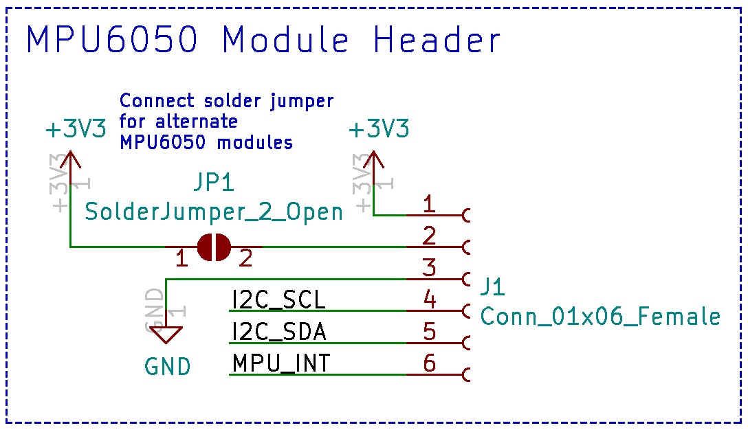
If you remember the PCB that I designed for the water level sensor, there were a few extra features on
that board that I hadn't used. One was this 6-pin header with i2c that I added specifically to accomodate an
MPU6050 module. In its default state, this header works with the Adafruit MPU6050 module I linked above. By
connecting the JP1 solder jumper, it also accommodates cheaper MPU6050 modules that can be found on Amazon.
The full KICAD files can be found here:
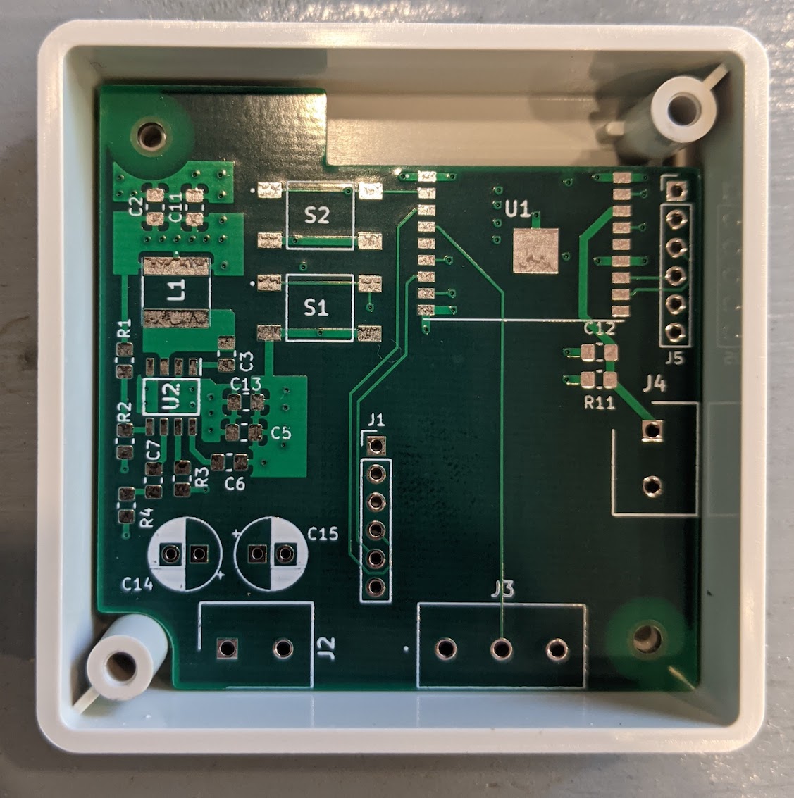
I forgot to take a picture of the assembled board, but you can see J1 in the picture above where the
module is mounted.
Next is the software for the ESP8266. Luckily there's functionality in ESPHome for the MPU6050, so the
software part is very easy. Details on this can be found here:
To create the new ESPHome file, open up the ESPHome dashboard (http://192.168.0.101:6052/ in my case) and click the plus button in
the bottom right. Choose "Generic ESP8266" and enter your wifi information. In the config file you'll then want
to add:
i2c:
sda: 2
scl: 14
sensor:
- platform: mpu6050
address: 0x68
update_interval: 200ms
accel_x:
name: "MPU6050 Accel X"
accel_y:
name: "MPU6050 Accel Y"
sda: 2
scl: 14
sensor:
- platform: mpu6050
address: 0x68
update_interval: 200ms
accel_x:
name: "MPU6050 Accel X"
accel_y:
name: "MPU6050 Accel Y"
This sets up the i2c pins (change these pin numbers if your configuration is different), then sets up the MPU6050
sensor. The default i2c address for the MPU6050 is 0x68. I set an update interval of 200ms. The only two
readings we then need from it are acceleration on the X and Y axes which can then be used to calculate the left
to right tilt and the front to back tilt of the van. I then programmed the ESP8266 and mounted it underneath my
bed.
With the ESPHome integration in Home Assistant, the new sensor was automatically detected and added. I
could now view the X and Y acceleration values from the device, but to make it more readable I wanted to convert
these values to degrees. With some digging around I found this equation:
tilt in degrees = arcsin(acceleration / gravity) * 180 / pi
Adding this equation into Home Assistant, I was now getting tilt readings on two axes in degrees. The
readings seemed a bit off though, so the sensor most likely needed to be calibrated. To calibrate, I used an app
on my phone to measure the tilt and set my phone on top of my bed platform. I took measurements with the van
parked at different inclines and averaged the differences to come up with an offset value. I also noticed that
the degrees readings were inverted from what I wanted, so I added a -1 multiplyer. The final equation was:
tilt in degrees = ((arcsin(acceleration / gravity) * 180 / pi) - offset) * -1
Here is the code I added to the Home Assistant configuration file to add this:
- platform: template
sensors:
x_angle:
friendly_name: "X Angle"
unit_of_measurement: "°"
value_template: '{{ ((asin((states("sensor.mpu6050_accel_x") | float) / 9.81) * 180 / pi) - 2.8) * -1 }}'
y_angle:
friendly_name: "Y Angle"
unit_of_measurement: "°"
value_template: '{{ ((asin((states("sensor.mpu6050_accel_y") | float) / 9.81) * 180 / pi) + 0.3) * -1 }}'
There also seemed to be quite a bit of noise on the sensor, so I added a low pass filter as well. It's not perfect, but it helps a bit:
- platform: filter
name: "Filtered X Angle"
entity_id: sensor.x_angle
filters:
- filter: lowpass
time_constant: 5
precision: 1
- platform: filter
name: "Filtered Y Angle"
entity_id: sensor.y_angle
filters:
- filter: lowpass
time_constant: 5
precision: 1
name: "Filtered X Angle"
entity_id: sensor.x_angle
filters:
- filter: lowpass
time_constant: 5
precision: 1
- platform: filter
name: "Filtered Y Angle"
entity_id: sensor.y_angle
filters:
- filter: lowpass
time_constant: 5
precision: 1
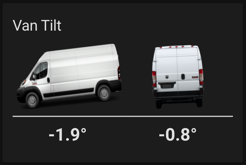
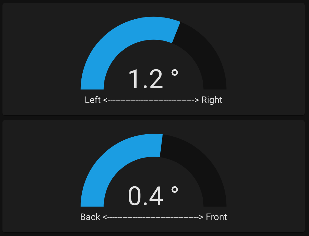
The end result is a Home Assistant sensor showing the tilt of the van which makes finding a level parking spot quite a bit easier.
Update: I wasn't very happy with how these sensors displayed in the Home Assistant interface, so I decided to make
my own lovelace card to better show this sensor output. Here is what it now looks like:
The code for this new card can be found here:
To install the card, create a new folder in your "homeassistant/www/" directory called "van-tilt-card" and
download the files to this directory. Then in Home Assistant go to Configuration - Lovelace Dashboards - Resources and click
"Add Resource". Enter "/local/van-tilt-card/van-tilt-card.js" for the URL and "JavaScript Module" for the type and click create.
Back in your main dashboard, you can now manually add the new card with the following code:
type: 'custom:van-tilt-card'
entity_x: sensor.filtered_x_angle
entity_y: sensor.filtered_y_angle
entity_x: sensor.filtered_x_angle
entity_y: sensor.filtered_y_angle